Smoke Ventilation Systems: Understanding the Schematic
What Is a Schematic?
A schematic is a diagram that represents how components of a system are connected and interact. In smoke ventilation systems, a schematic shows:
- Smoke detectors and manual call points (inputs)
- AOVs, fans and alarms (outputs).
- Smoke control panels with power supplies and backup systems
In essence, the schematic provides a roadmap of system operation, enabling accurate installation, commissioning, and maintenance.
Why a Schematic Is Critical?
A smoke ventilation system schematic is more than a technical drawing – it ensures the following are followed:
- Proper installation and wiring.
- Compliance with fire safety standards.
- Effective coordination between zones, vents, fans, and control panels.
- Clear fault detection and monitoring for maintenance.
Teal Products is a manufacturer and supplier of natural and smoke ventilation solutions. For assistance on your project, please contact us today.
Single-Zone vs Multi-Zone Smoke Ventilation Schematic
A smoke ventilation system schematic can be designed for either single-zone or multi-zone operation. The distinction lies in how many areas (or “zones”) are controlled independently, and how the inputs and outputs are linked.
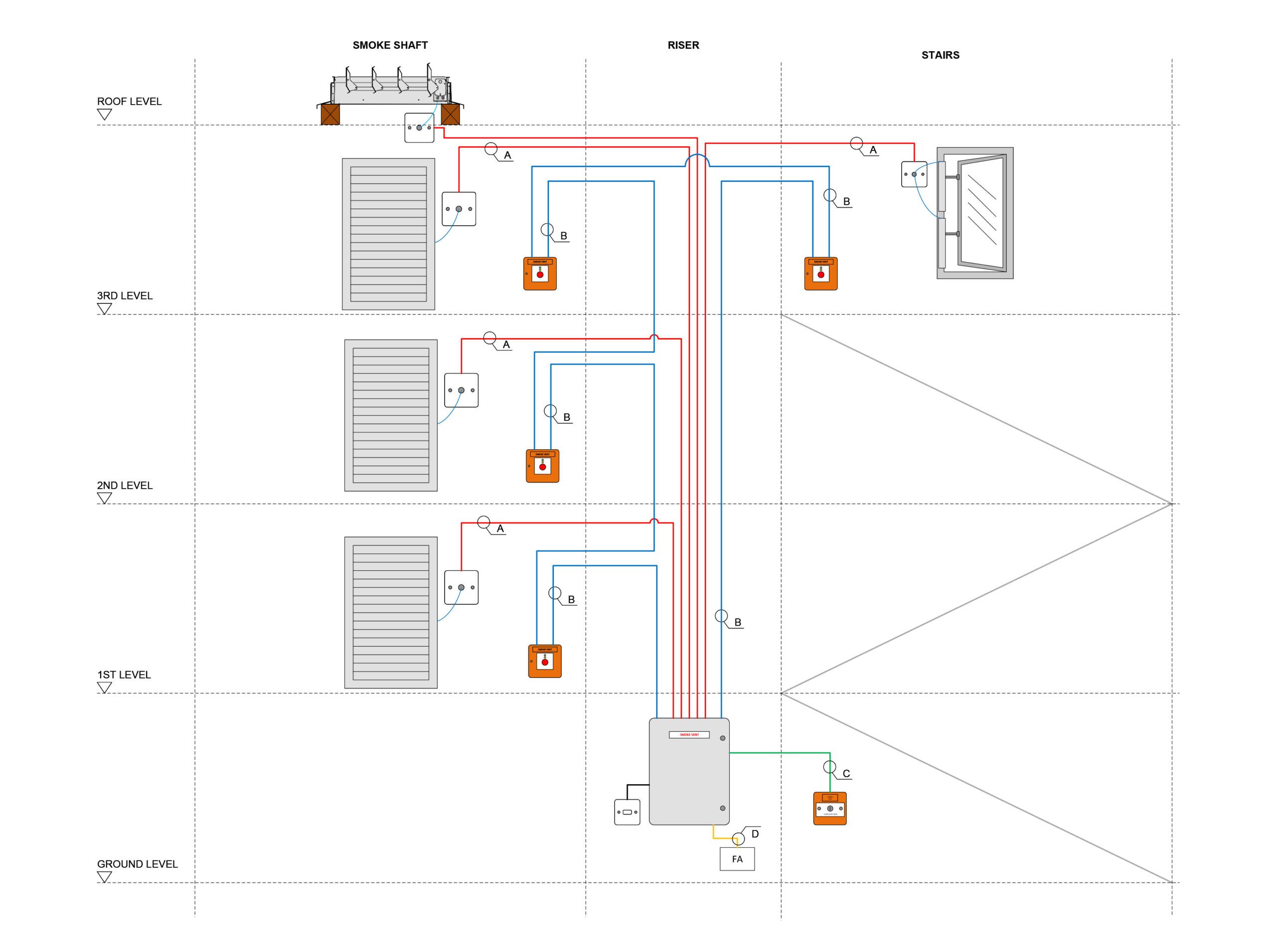
Single Zone Schematic
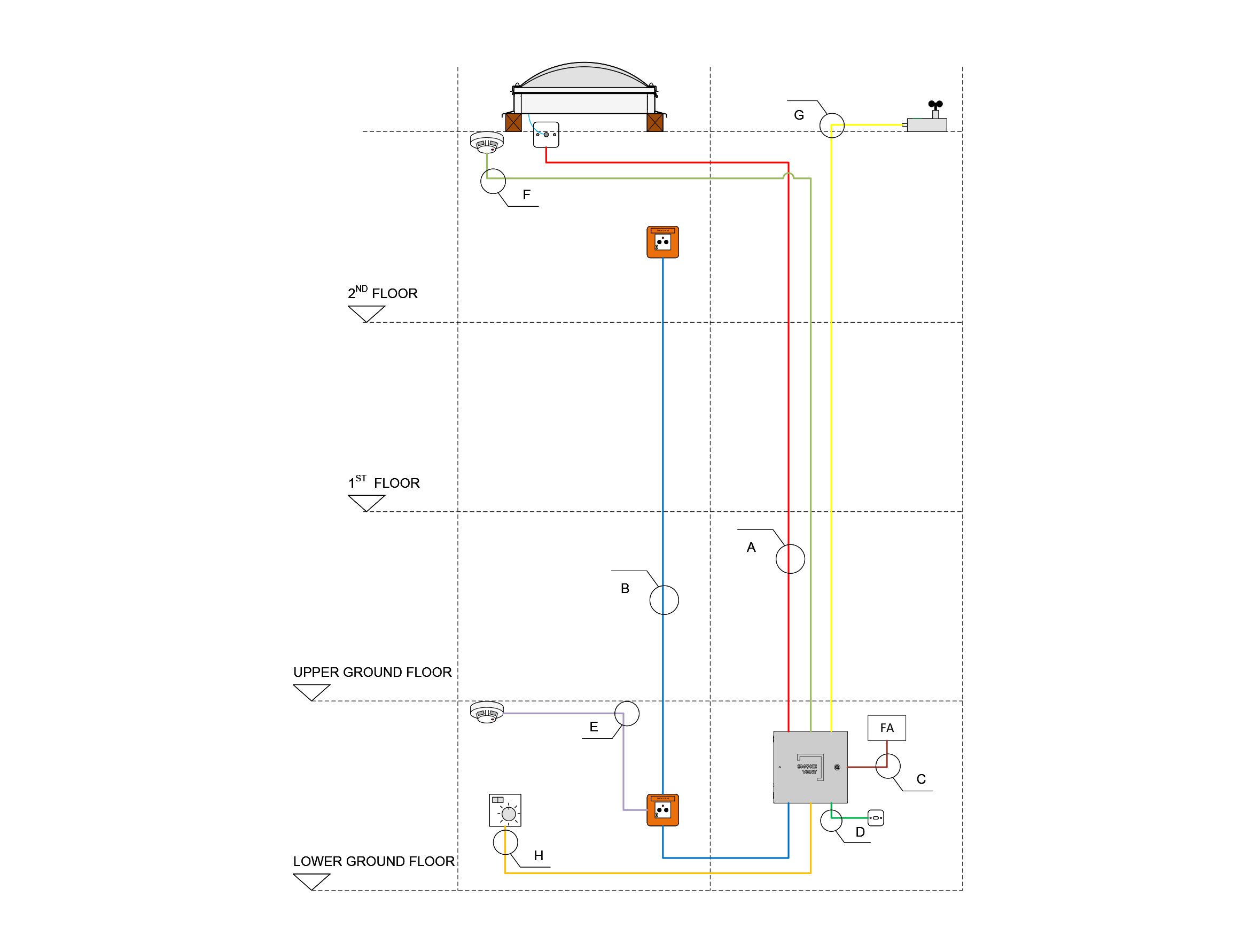
A single-zone system manages smoke ventilation in one controlled area, such as a single stairwell, lobby, or a small building section. All smoke detectors and vents in this zone are linked to one control panel.
- One smoke control panel with integrated battery backup.
- Smoke detectors and manual activation points (break glass units, firefighter override) feed directly into this panel.
- All vents (AOVs, louvres, rooflights or smoke dampers) in the zone are controlled together.
- Fans (if used) are activated in sync with vent operation.
- HMI/status displays show the zone as a single block, without separate independent outputs.
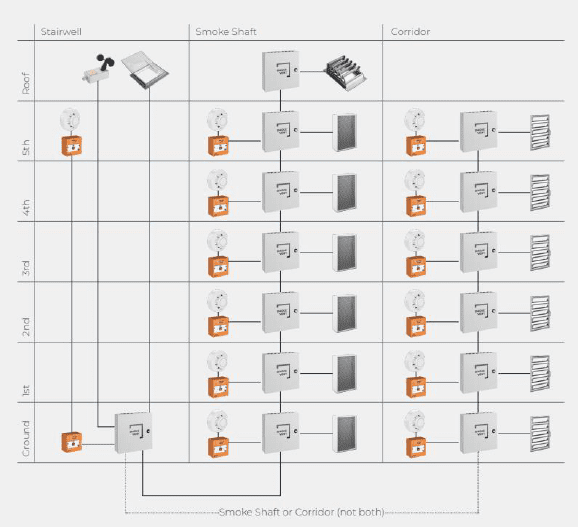
Multi-Zone Schematic
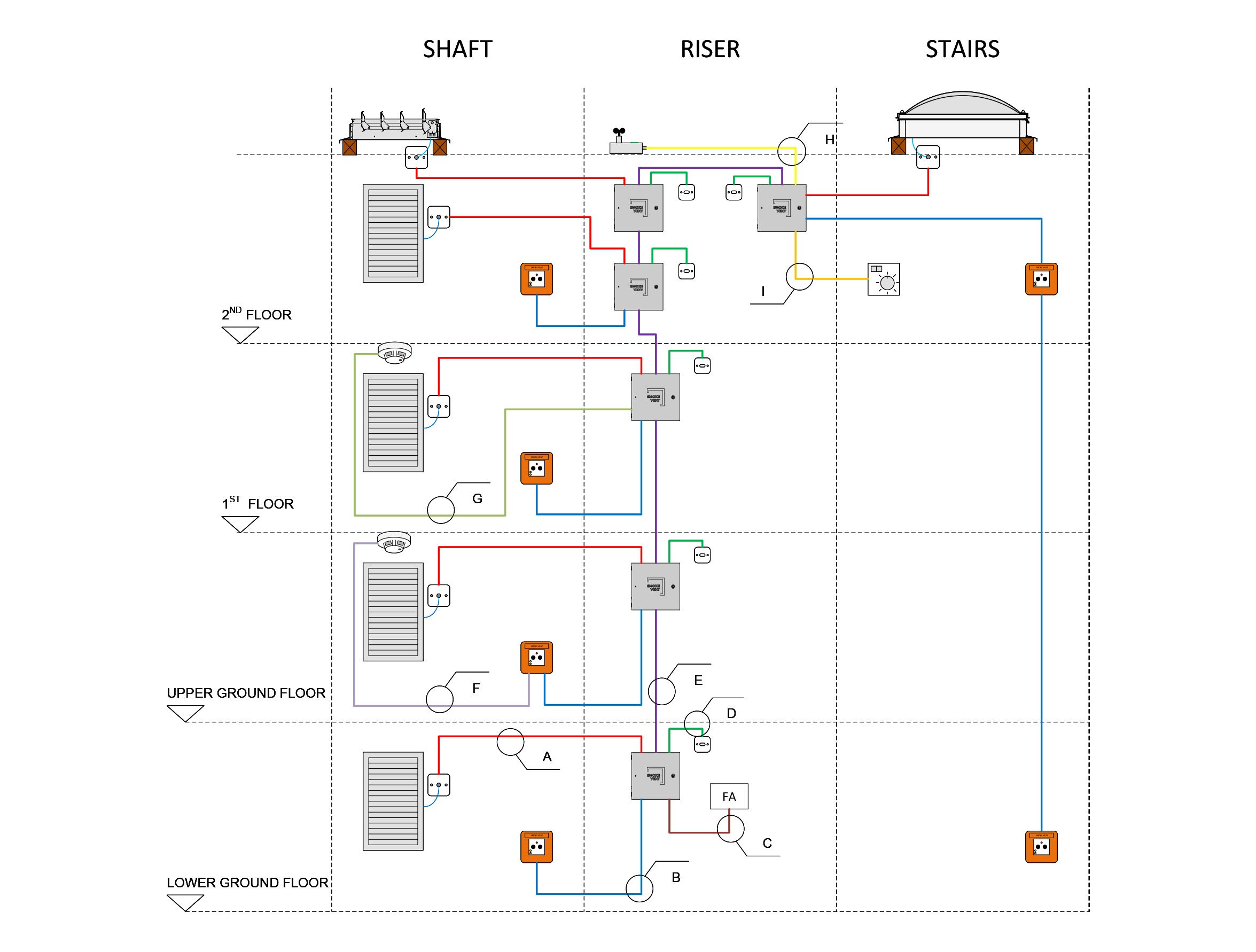
A multi-zone system controls multiple independent areas, such as stairwells, corridors, and smoke shafts in larger buildings. Each zone can respond individually depending on where smoke is detected.
- Multiple smoke control panels (can be networked in a master-slave configuration).
- Smoke detectors and manual activation points in each zone feed their respective panels.
- Vents, dampers, and fans in each zone operate independently, only when smoke is detected in that specific zone.
- Master panel can coordinate zones, e.g., locking out unaffected zones to avoid unnecessary venting.
- HMI/status displays show each zone separately, often with color-coded feedback.
Need help with your project?
Designing, installing, and commissioning a smoke ventilation system can be complex, particularly when managing AOVs, fans, multi-zone logic, and fire safety compliance. A well-prepared schematic is essential to ensure reliable system operation, but translating it into a functional installation requires both skill and experience.
With over 25 years of expertise, Teal Products provides high-quality natural and smoke ventilation products tailored to your projects. Our commitment to technical excellence and exceptional customer service has made us a trusted name in the industry. For professional guidance on your smoke ventilation project, contact us today.